The finished boxes, ready to send out
Background
I decided to make something fun for my teammates to hack on during a team offsite in France. Although I didn’t end up bringing these overseas, I still wanted to detail how they were made, what was involved.
Each puzzle box has a couple of games, using some of my favorite sensors for the Arduino.
Game 1
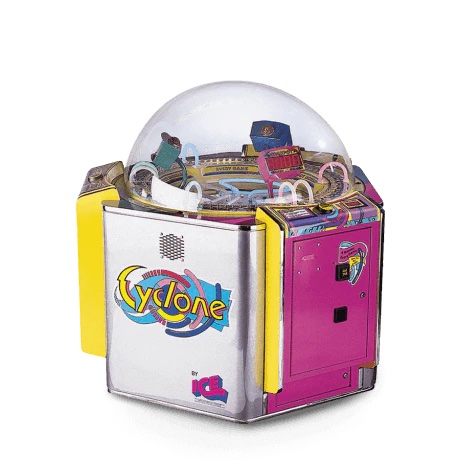
I stole this game from this arcade machine
The first game is a simple “stop on the light” game. The LEDs are cut from a big spool of Adafruit NeoPixels in sections of five pixels, and then soldered to form a square.
Game 2
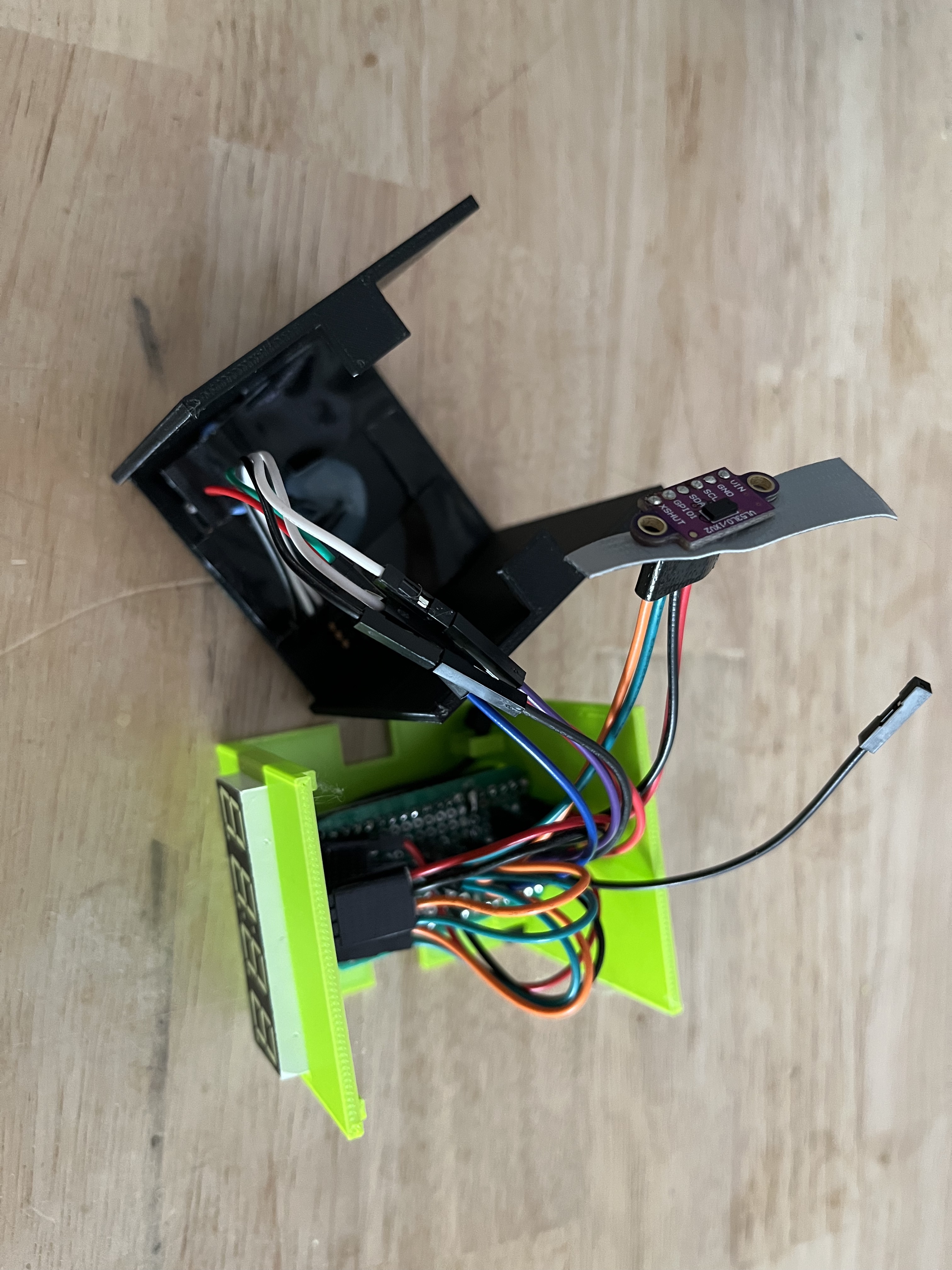
Hot-glued into a small pinhole on the side of the box is a VL53L0X ToF sensor.
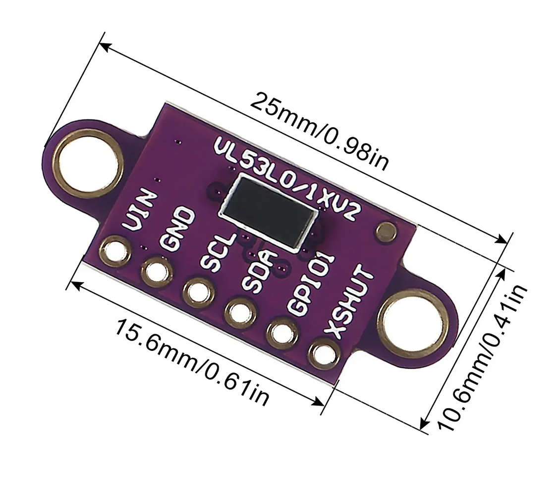
It’s no Sony IMX556PLR, but it has incredible 1pixel <1m precision
The second game picks a random distance, and requires you to move an object in front of the ToF beam until it matches the calculated distance.
Game 3
The third game picks a random orientation and requires the 3-axis gyro to be oriented in the direction.
Development
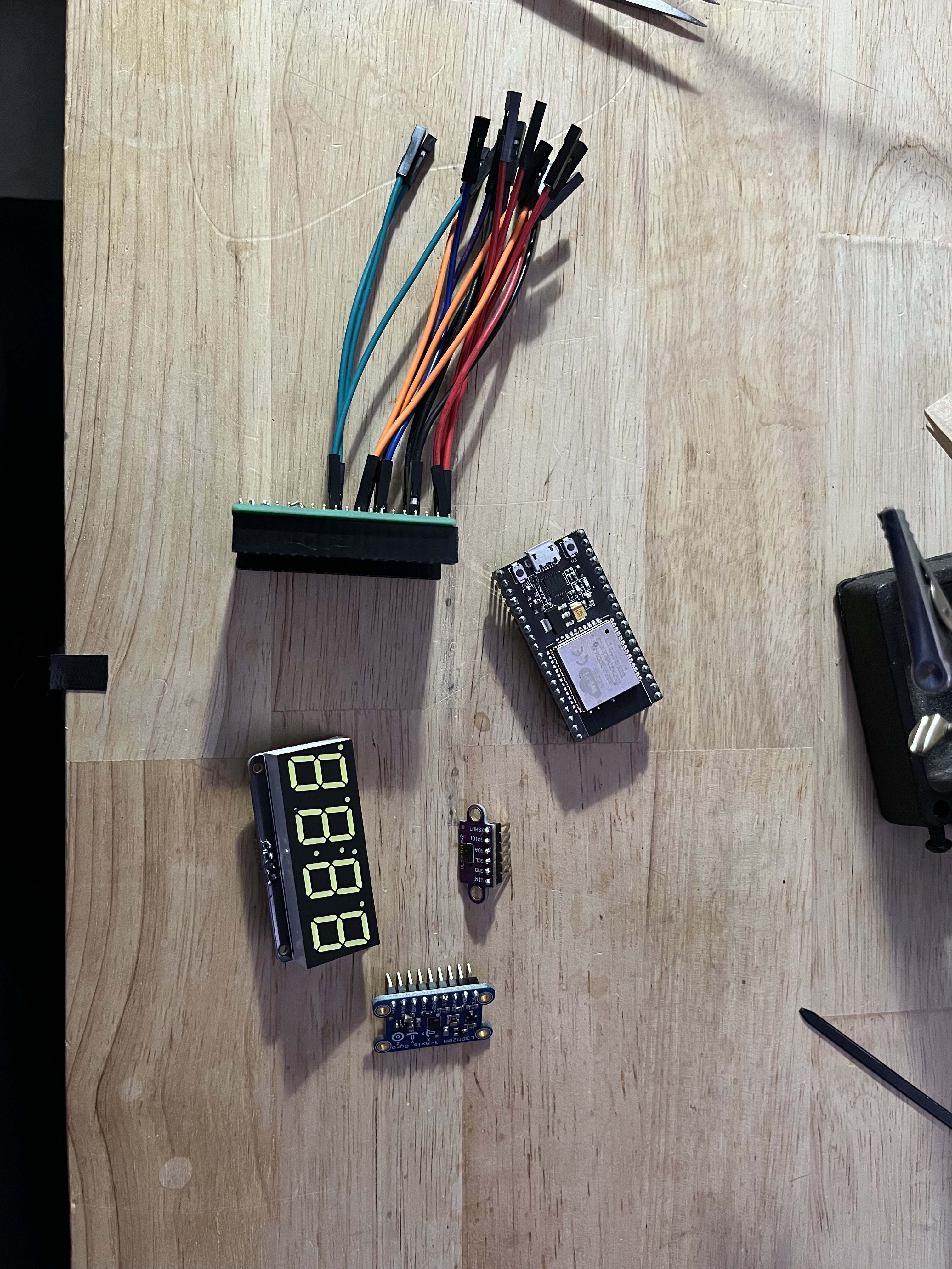
The final BoM for each box looks like
- 1x ESP32
- 1x 7-segment display
- 1x L3GD20H
- 1x VL53L0X
- 1x Mini Soft Touch Push-button
- 20x NeoPixels
- 1x 10k resistor
- 18x male-to-female breadboard jumper wires
- 1x permaproto board
- 2x 19pin header rows
- 1x printed enclosure
- and a whole mess of epoxy
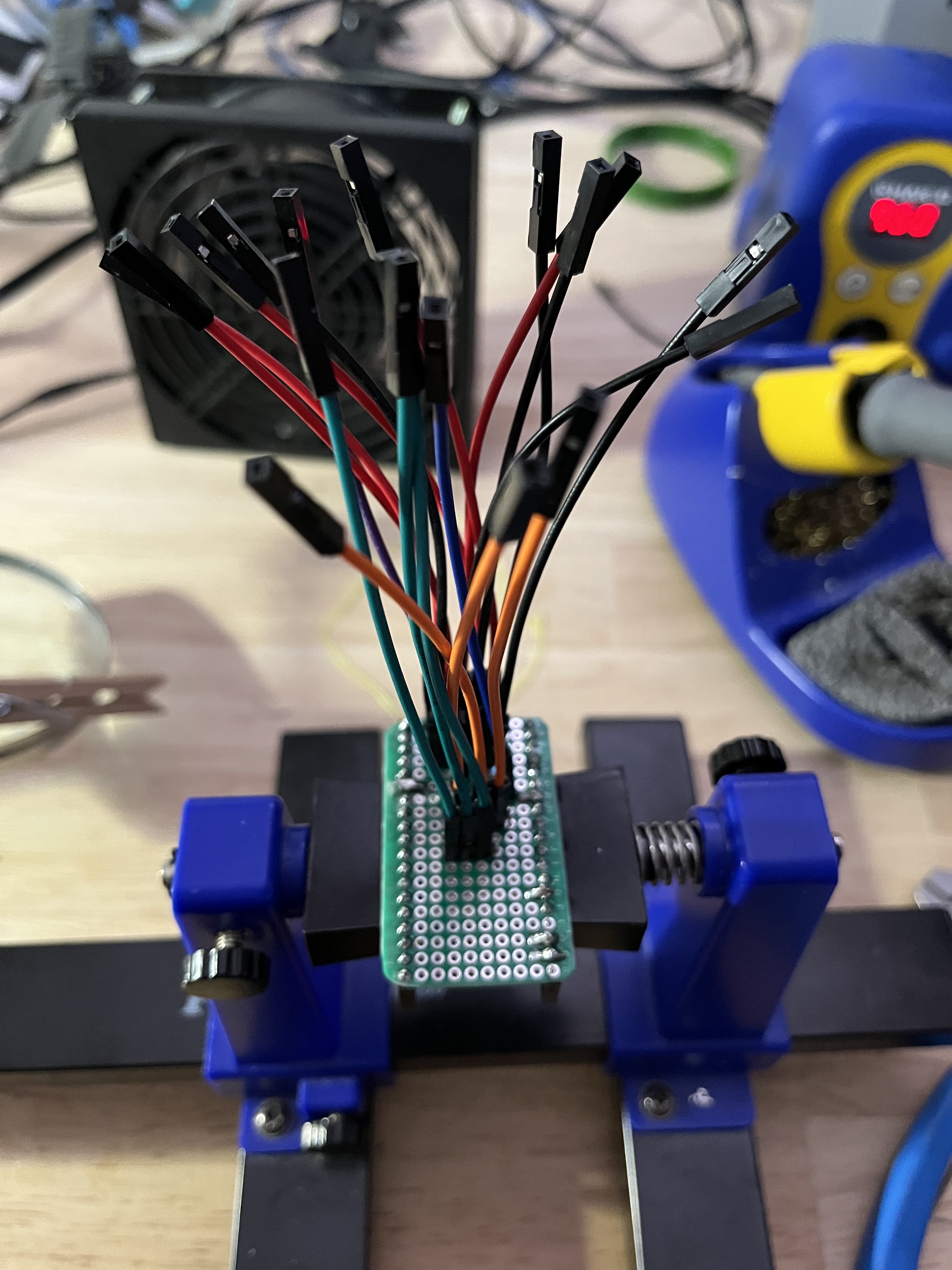
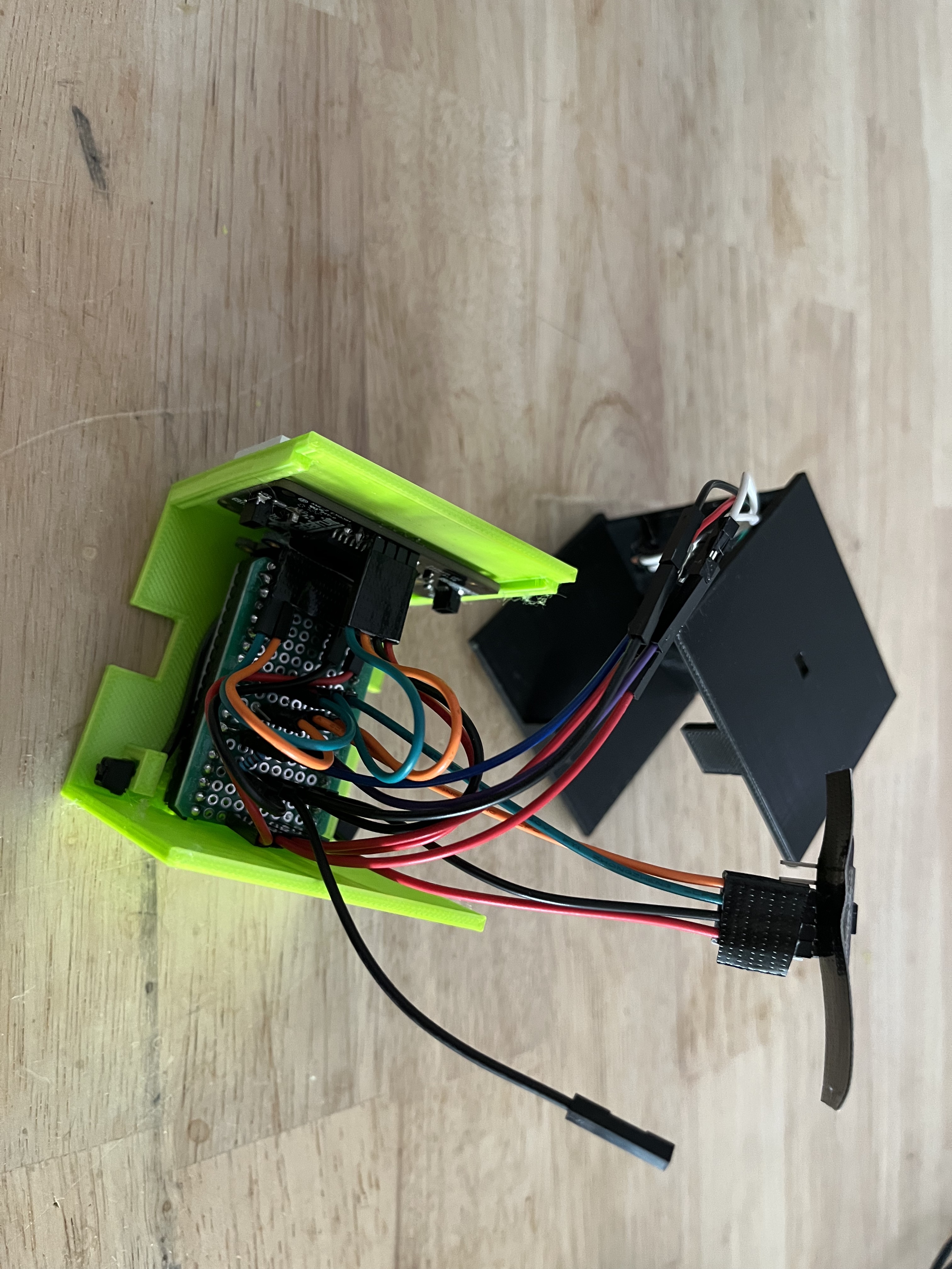
The wiring harness, which breaks the ESP-32 pins into specific connectors for each sensor
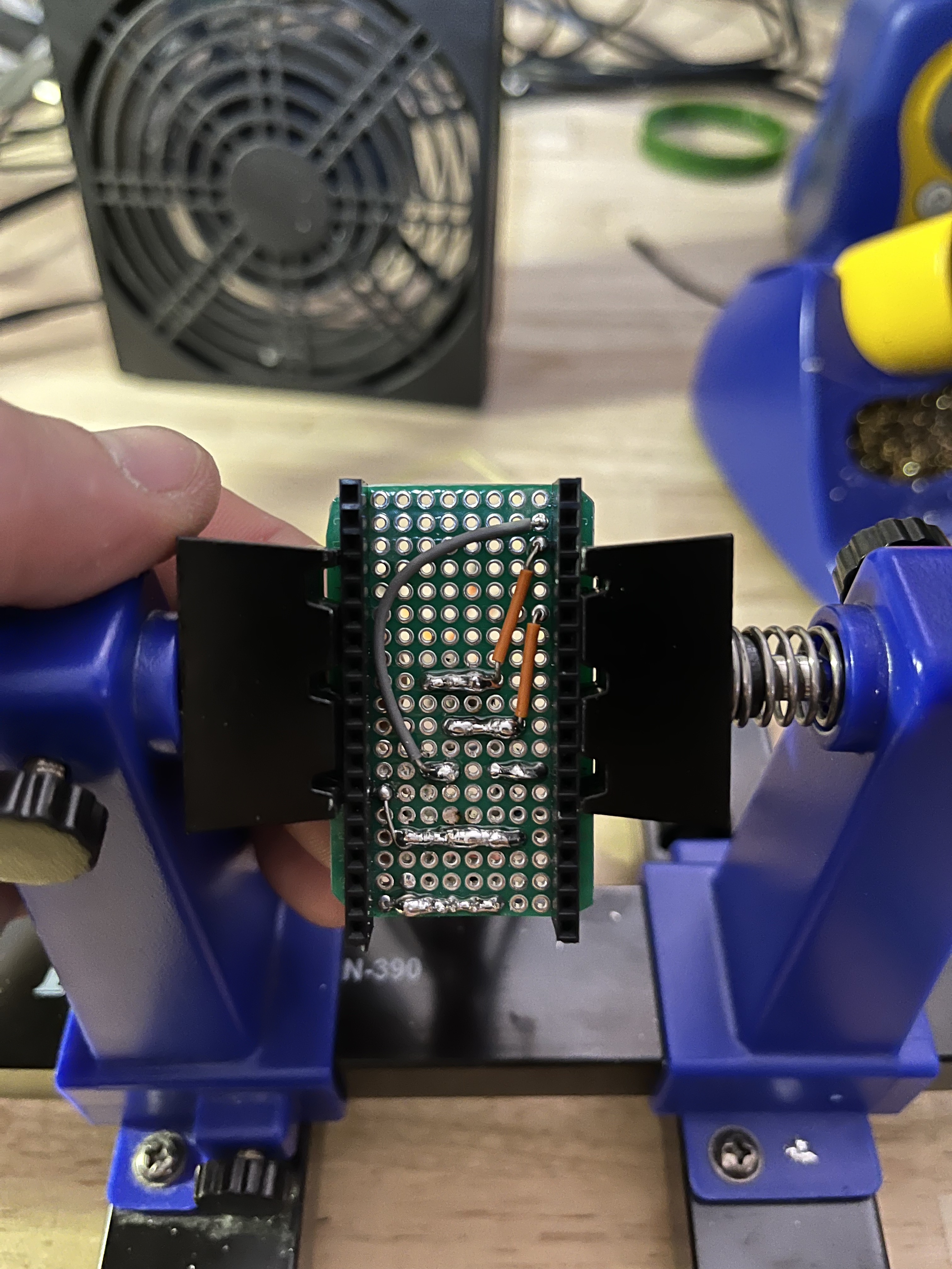
The back of the harness, where the ESP-32 plugs into. The bottom two rows are voltage / ground, the middle is button / resistor / neopixel pins, and the top two rows are I2C SDA and SCL buses
Assembling was so much fun!
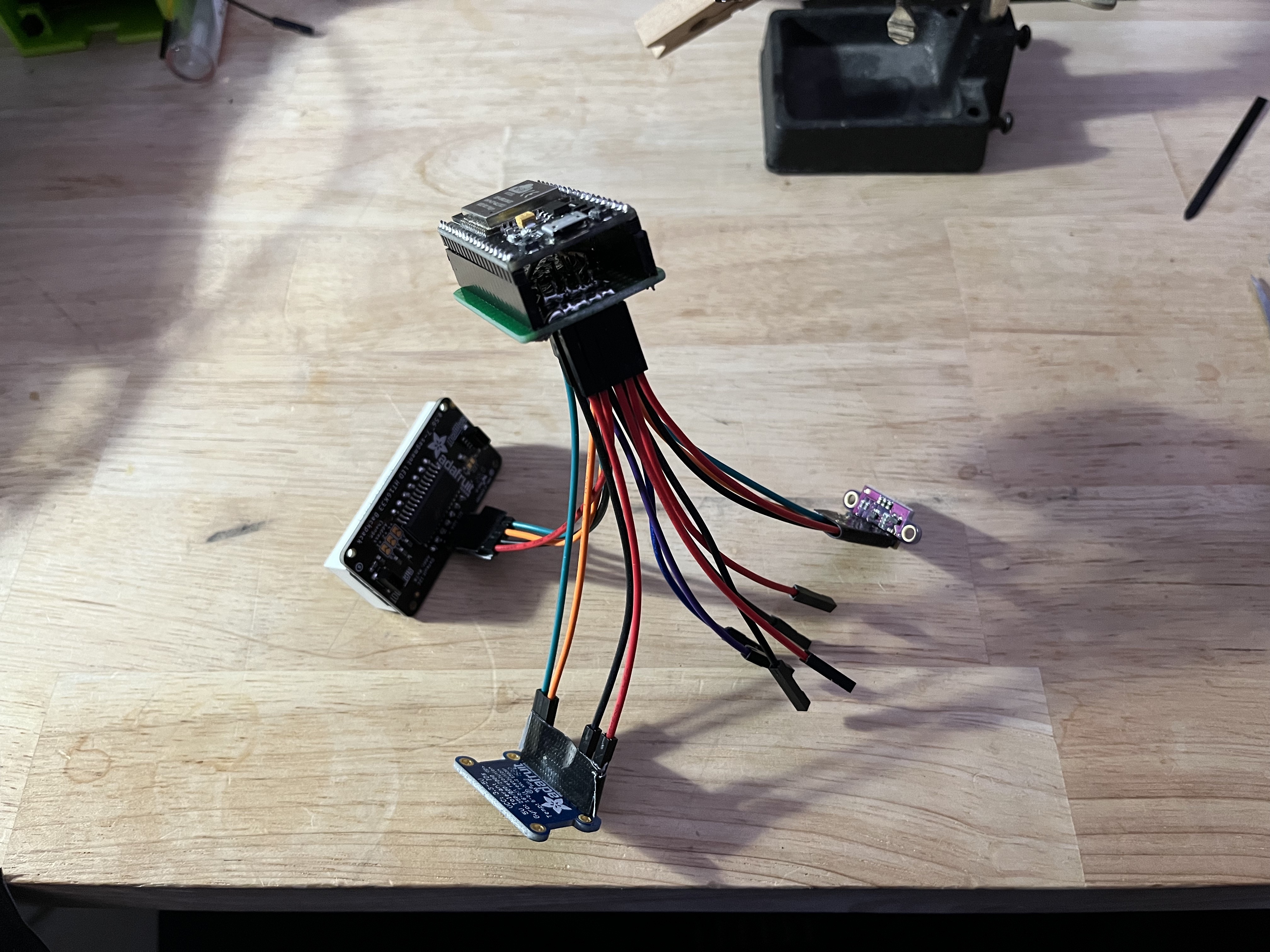
Most of the parts could be tested outside of the box to ensuring the connections were good
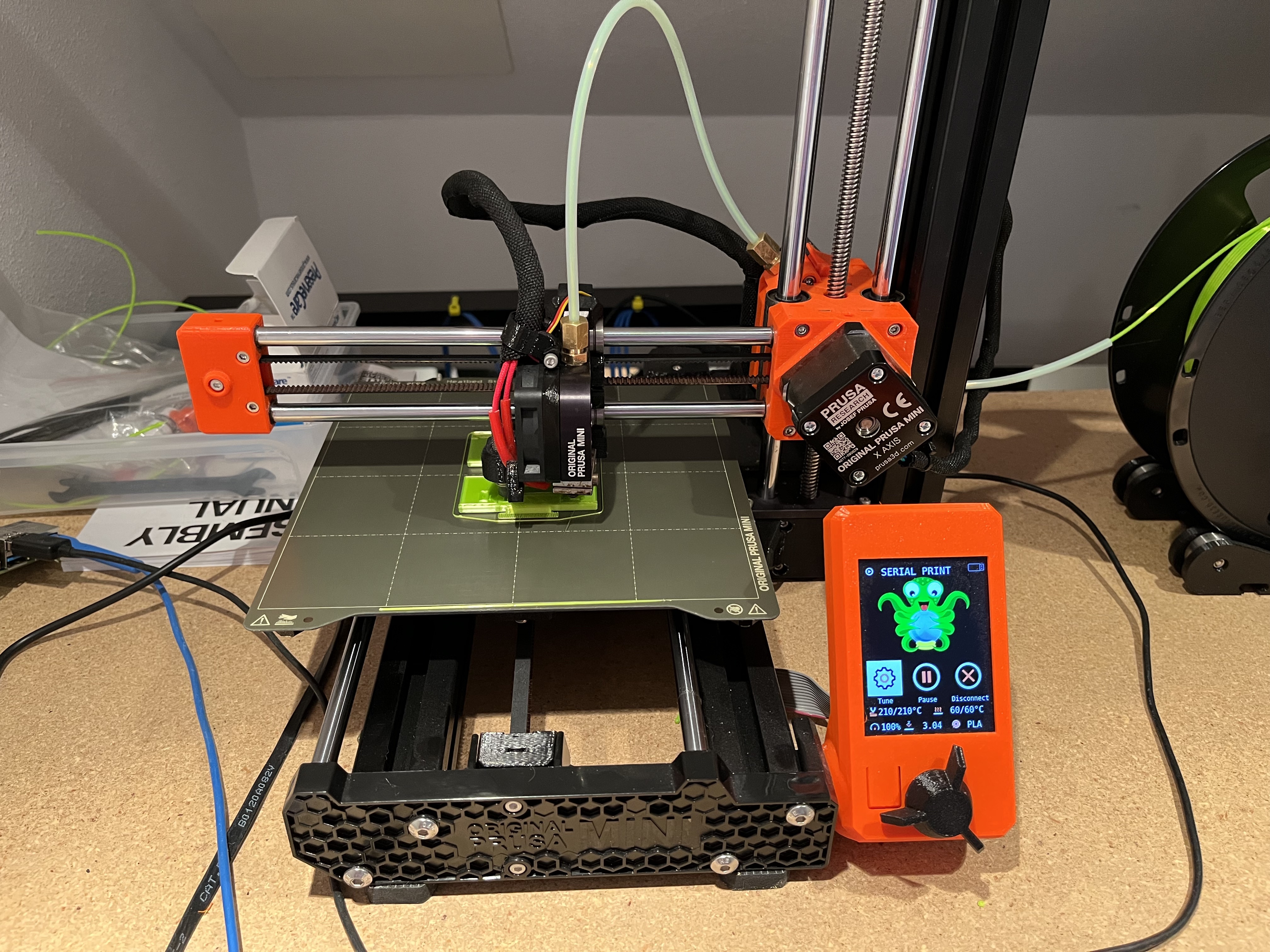
Prusa Mini printing a box
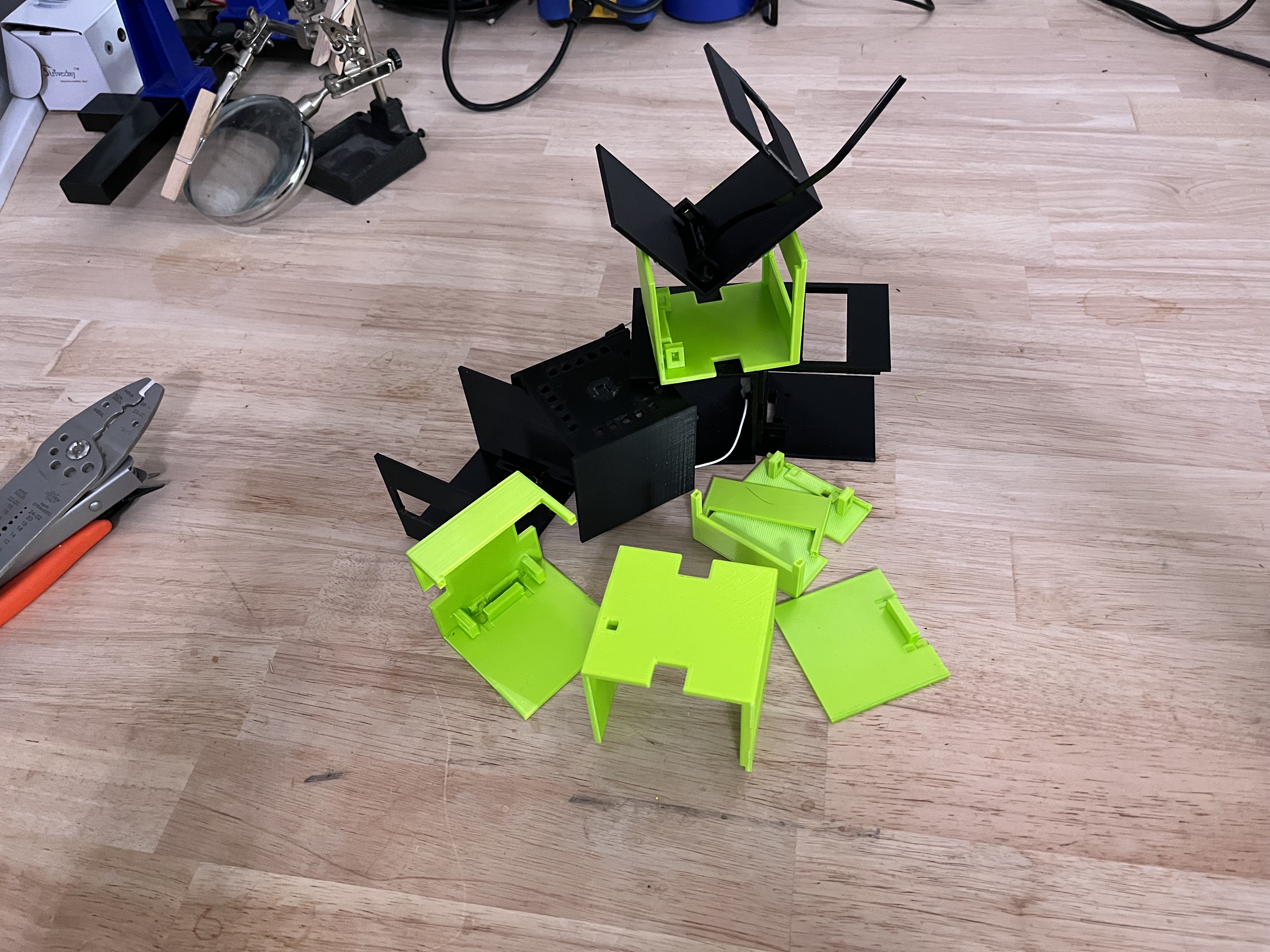
I made many mistakes designing the box
Starting to assemble the parts into the box
Another picture of parts in the box
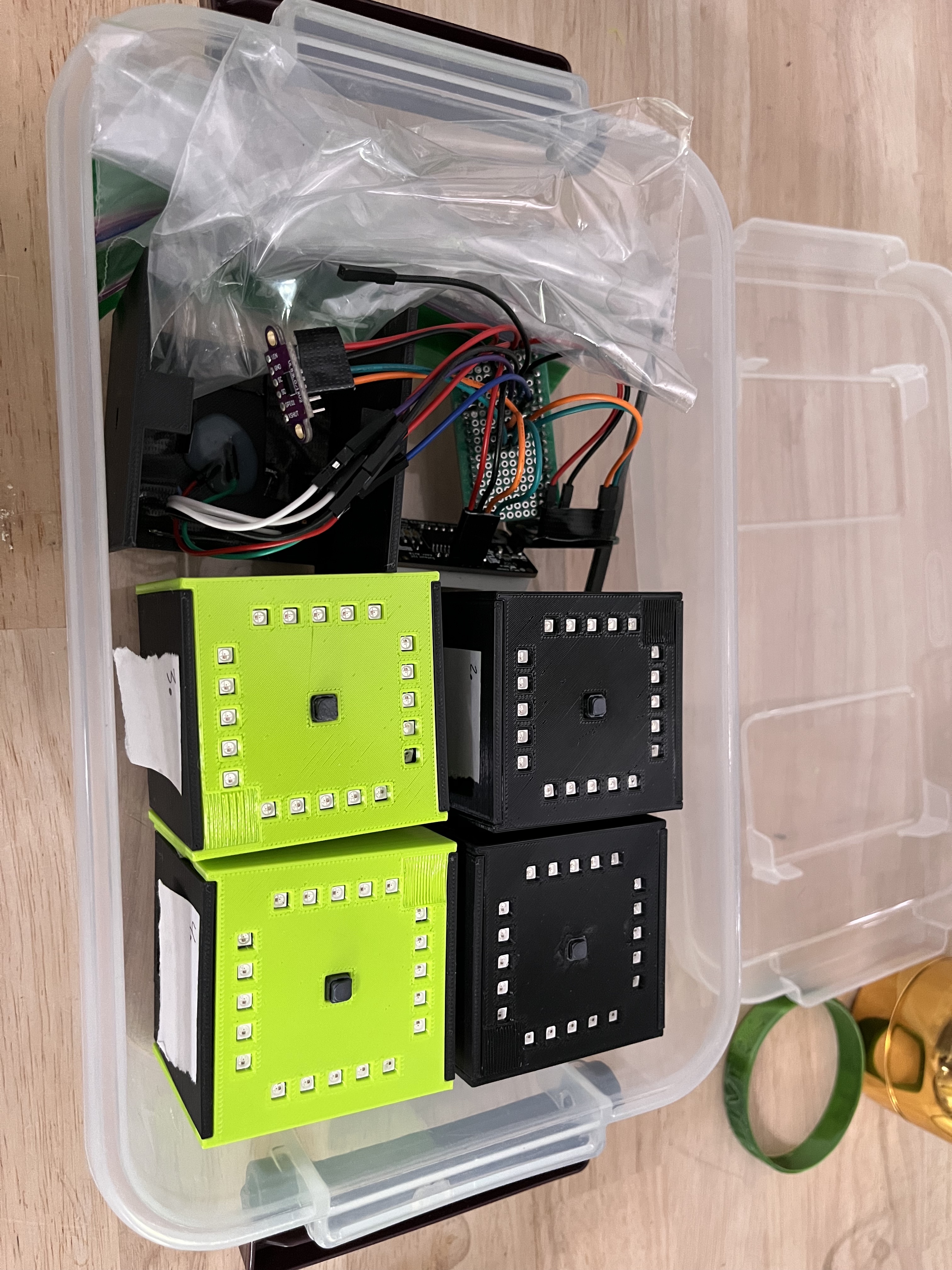
Boxes assembled and ready to ship!